Setup & Calibration
Initial Setup
Compile the firmware using the Arduino IDE or
arduino-cliand upload it to your Arduino board.Open a serial connection to the board with a baud rate of
115200.Check that the board connects successfully by looking for the
READYmessage in the serial monitor.
Checking Motor Directions
Before running any automated movements, make sure the physical rotation of each motor matches the software’s expectations.
Disconnect motor power and manually move the arm into the mechanical home position:
Send the
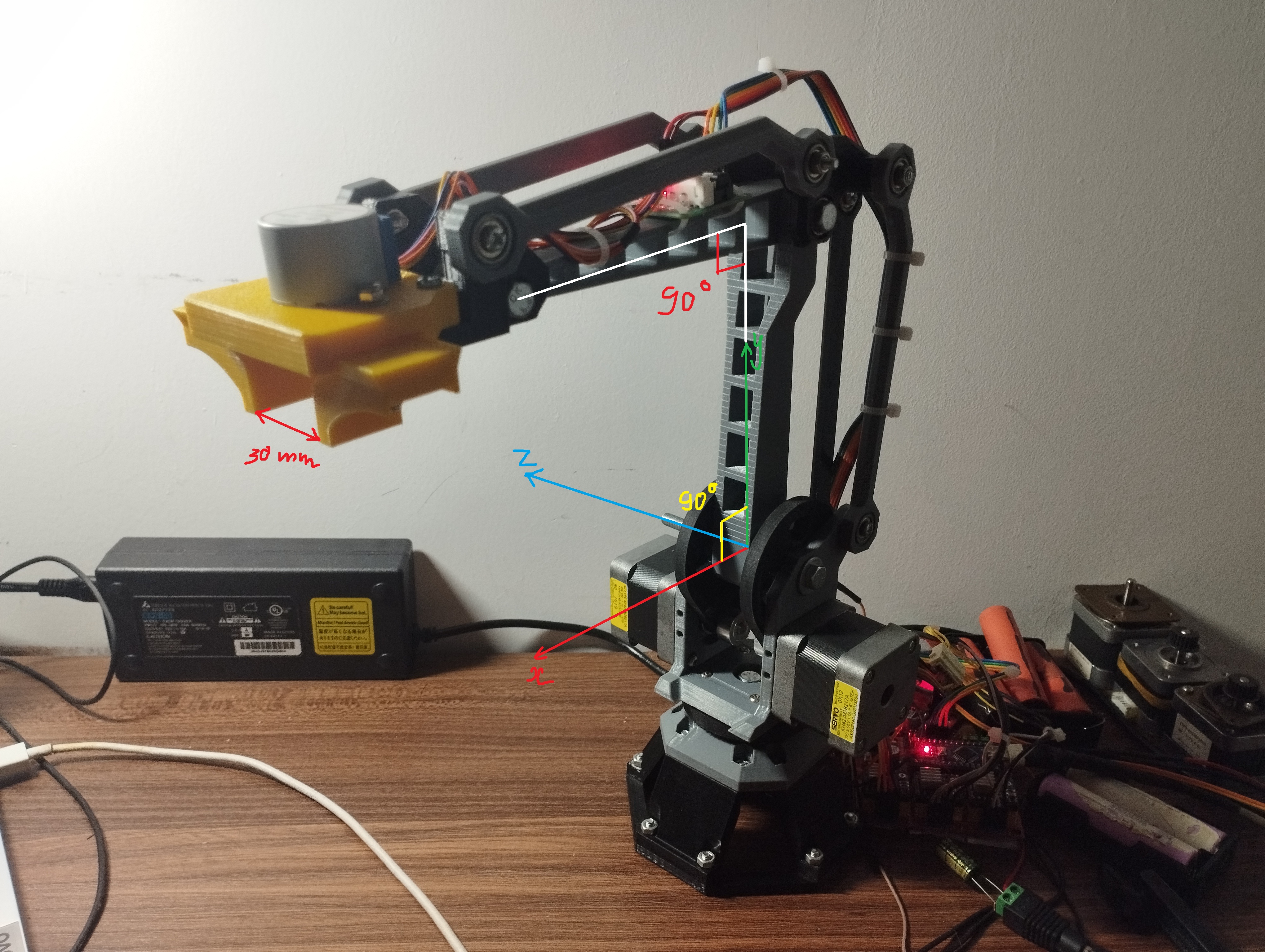
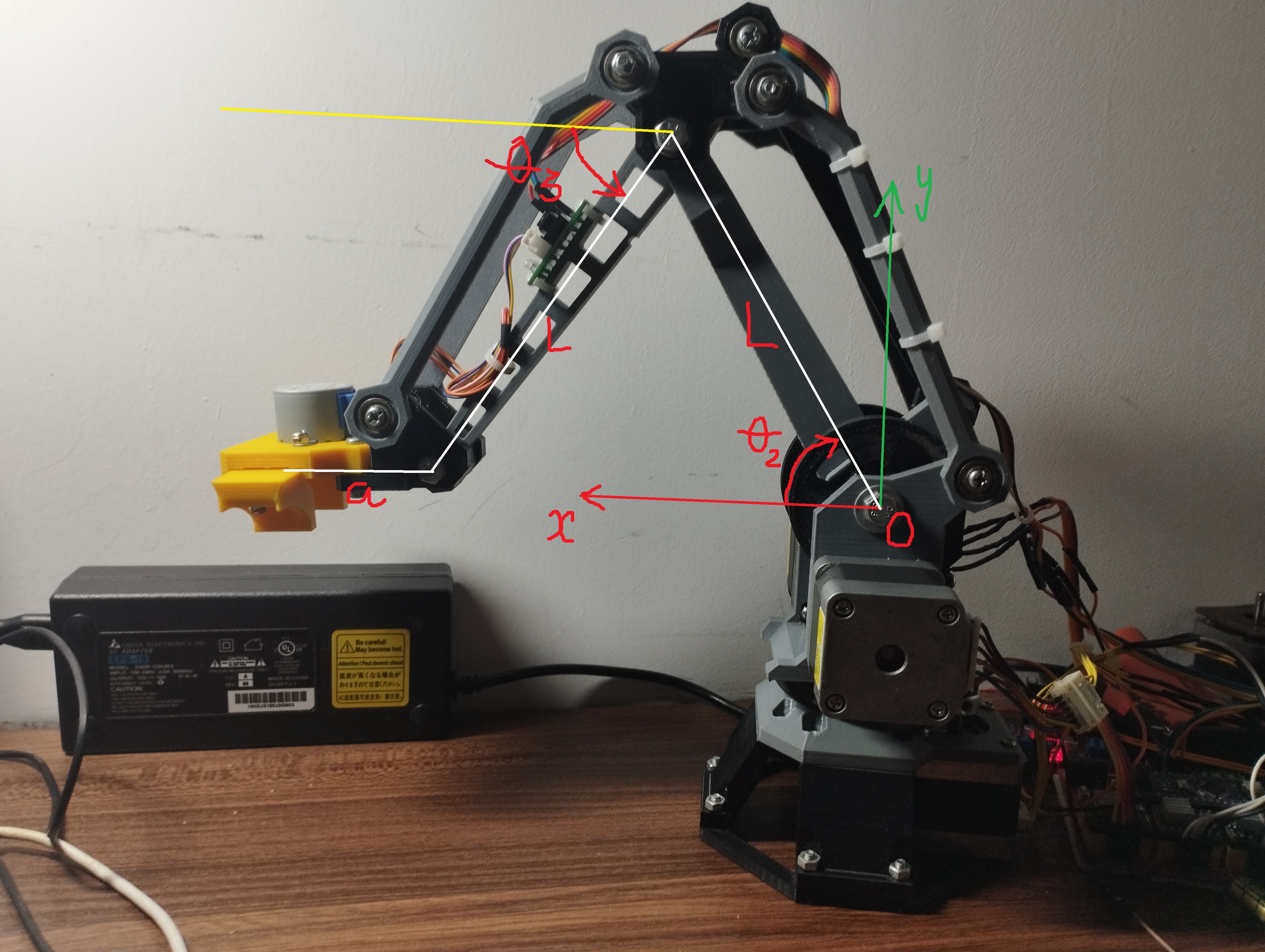
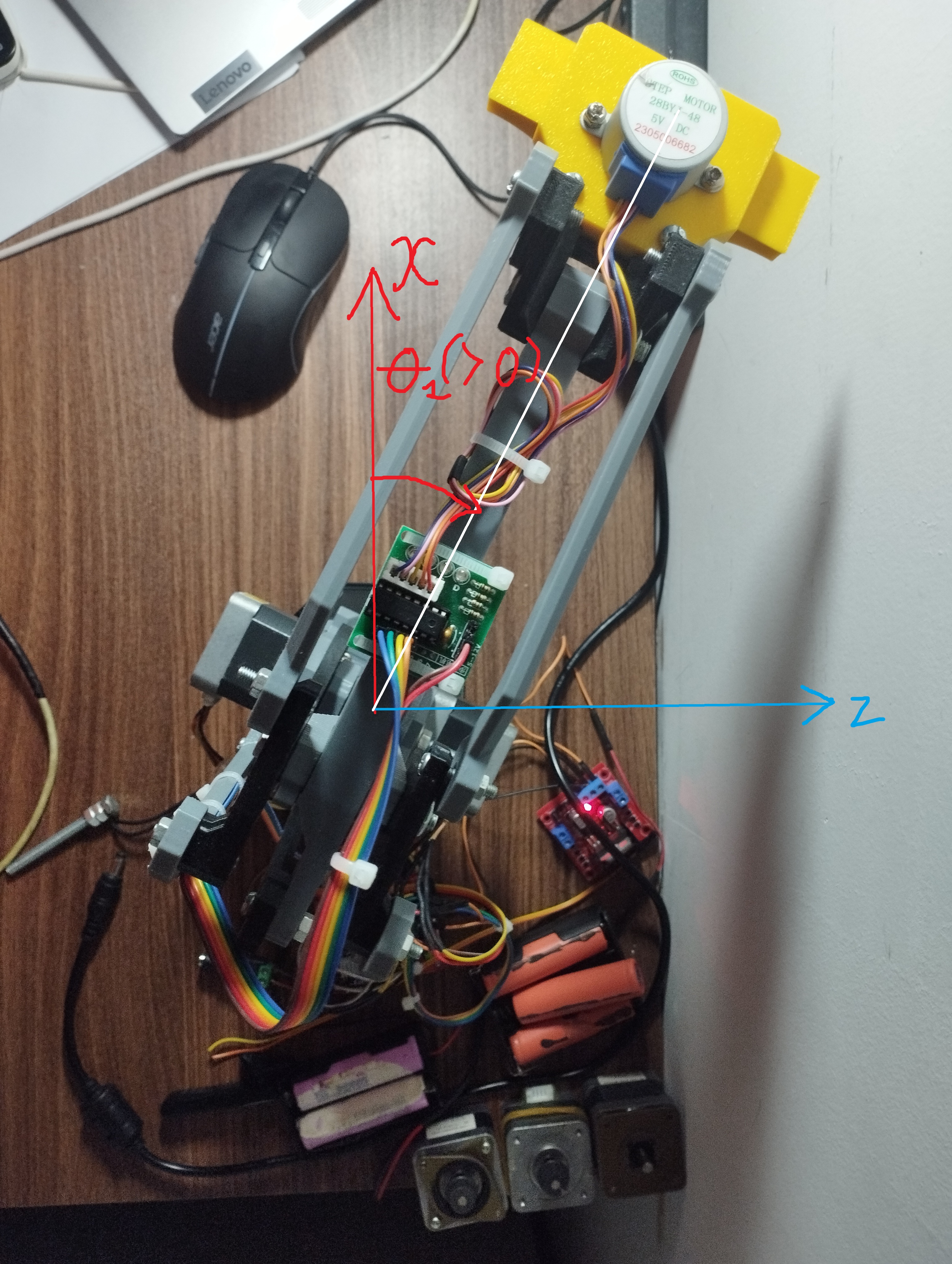
M17command to turn on the motors. The joints should lock in place.In this position, the software assumes the internal joint angles are: Theta 1 = 0°, Theta 2 = 90°, and Theta 3 = 0°.
Reference the coordinate diagram below to understand the defined positive rotation vectors:
Move each joint a little bit using absolute positioning commands (e.g., send
G1 T145to move Theta 1 to 45°). Note that relative positioning (G91) does not work for direct joint commands (T-parameters).If a motor turns in the wrong direction:
Software Fix: Change the direction in code by toggling the
MOTORx_INVERTsetting inConfig_Robot.hand upload the code again.Hardware Fix: Turn off the power and swap the coil wires for that stepper motor.
Testing Limit Switches
Caution: Homing the arm with broken limit switches will cause the arm to crash and potentially break hardware.
Send the
M119command to check the limit switch status.Make sure all switches show as open (
0for default setups).Manually press each limit switch one by one while sending
M119again to confirm they change to triggered (1).
Auto Homing
Send the
G28command to start homing.The controller will move all joints toward their limit switches.
When a switch is hit, the system moves back by a set number of steps and sets the internal angles to the home position.
Emergency Stop
If something goes wrong or the arm is about to crash:
Send the
M112command (or just!) to trigger an immediate software stop. This immediately cuts the ENABLE line to the motors.After a software stop, you must run a full
G28homing cycle before moving the arm again.Hardware Override: Physically unplugging the main DC power supply is always the safest way to stop the robot.
Calibration
Steps Per Degree
The STEPS_PER_DEGREE setting tells the software how many motor steps equal one degree of movement. It needs to be calculated based on your motor, microstepping, and gear ratio.
Home Offset Calibration
The HOME_OFFSET_STEPS_THETA* settings control how many steps the arm moves away from the limit switch after hitting it.
To calibrate the home position:
Run a full homing cycle (
G28).Check the current software position with
M114.Measure the actual physical angles of the robot.
Calculate the difference between the software angles and physical angles, convert this difference into steps, and update the offset numbers in the code.